

Home: Military
Please Note: Not all of the objects on this website are on display at the museum.
|
Shells, grenades, weapons and militaria. |
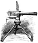
Hiram Maxim and the Machine Gun |
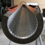
Spin It - What makes a Rifle work? |

Larger image |
GERMAN TELEPHONE EXCHANGE 10 LINE Known as a Small Flap Cabinet, or Klappenschrank in German (Clapboard). Switching is achieved by loose cords and plugs, with flaps on the front to indicate that a phone has been lifted, buttons on the front can select one circuit at a time presumably for the operators headset. Dated 1940. A1446 |

Larger image |
ELECTRONIC ENIGMA-E, 2009 Paul Reuvers and Marc Simons in the Netherlands decided to make this machine in 2001, after much research and overcoming many problems it was launched as a kit in 2003, it is much smaller than the real thing and is built around an original 4-rotor type machine. It does exactly what the original electro mechanical version did but using modern electronic components and software created by them. Two or more machine can encrypt and decode messages in the same way as the original. It has replaced the normal coding wheels with a led display and the patch board (Steckerbrett) on the front with normal links as in the original but with different plugs. Changing the days code would be done by up and down buttons above and below the LED display. The message to be decoded is entered on the keypad and the result of each key pressed is displayed momentarily on the illuminated panel above as in the original. A technical explanation of how the original machine worked together with all the variants that were produced. The idea was conceived in 1918 by German engineer Arthur Scherbius and Patented under the name Enigma in 1923 they were produced up to World War Two and used until the 1950's. In 1944 an addition was added known as the 'UHR' a 40 position switch which connected into the plug board. An electronic kit is also available for this unit. A1682 |

Larger image |
RACAL SPIKE ANTENNA, circa 1980 Ground spike for ten section aerial complete with lead and carrying case. Using the spike to create a ground connection transmission would be improved. By varying the length of the number of section of the aerial it can be matched during transmitting for 30 to 76 MHz. More sections are available out of the ten supplied for other frequency's. Be the first to write a comment about this objectA1667 |

Larger image |
SIGNAL LAMP/TORCH Possibly naval, because of the colour of the paint, at the end is a broad arrow, indicating that it was made for the war department, or government property. The lens is red but this can be removed to reveal a further clear glass lens inside to provide normal torch use. At the rear of the unit is a key that can be retracted for protection, providing a Morse signalling application. Underneath at the rear, is a bracket to provide stability when the key is in use. See Item A1601. Be the first to write a comment about this objectA1602 |

Larger image |
LEADS COUNTERPOISE No2 Mk2, 1950's No. 2 Mk II Counter-Poise for the Wireless Set No. 19 antenna, and similar. The Counter-Poise has four wire segments which are laid like a cross underneath the radiating antenna. The four wires terminate to a central location at the radios earth terminal to provide an artificial ground plane. Each wire segment is 340 Cm Long. A1518 |

Larger image |
HEADSET No10 PACKED, 1952 Headset No10 for the Wireless Set No19 in original packing, this item literally fell of the back of a lorry in 1952, and is dated April 52. for a view of the headset see Item No A0095 A1515 |

Larger image |
HEADSET No10 FOR WS19, 1950's One type of Headset and microphone used for the Wireless Set No19. Item A0088 and A0871, and WS62 Item A1405. View 2 comments about this objectA0095 |

Larger image |
WWII TYPE F FANY HEADSET, 1940's Headset used by The First Aid Nursing Yeomanry F.A.N.Y. as part of the S.O.E. Special Operations Executive. The First Aid Nursing Yeomanry was created in 1907 by Lord Kitchener, as a link organisation between front line fighting units and field hospitals. A0488 |

Larger image |
HAND PEDAL GENERATOR Mk810A, 1950's The Mk810A generator also known as 'Generating set AC 45W 110V, hand or pedal driven, No1 Mk1' was intended for powering AC powered equipment such as receiver Mk122 or Mk123. The unit can be pedal or hand operated, and is supplied with all the suitable accessories, on the top of the main unit is a meter indicating up to 150V with two red marks between which the needle should be held whilst turning the pedals. The base plate comes with a chain so it can be attached to a tree trunk or other similar object, also supplied are two clamps for table mounting. The whole unit and parts pack into the box supplied. A1461 |

Larger image |
WW11 CARRIER PIGEON MESSAGE TUBE Attached to the pigeons leg and containing a small rolled paper message, sometimes as thin as a human hair. A1295 |

Larger image |
WWII FANY MORSE KEYS Silent Keys used by The First Aid Nursing Yeomanry F.A.N.Y. as part of the S.O.E. Special Operations Executive. View 3 comments about this objectA0485 |

Larger image |
WWII SG BROWN HEAD SET War Department issue DLR headphones of WW2 made by S.G.Brown. View 1 comment about this objectA0752 |

Larger image |
WWII ADMIRALTY SIGNAL LAMP, 1944 Admiralty Pattern 378A signalling Heather type. Previously A1110 |

Larger image |
WWII MORSE TRAINING SET Morse Training set for War Department Wireless Operators View 3 comments about this objectA1098 |

Larger image |
WWII US SIGNAL CORPS MORSE KEY, 1943 Morse key from WW2 in original box. View 2 comments about this objectA1102 |

Larger image |
WWII BC221-M WAVEMETER Used for Calibrating wireless transceivers. 125KHz to 20MHz heterodyne frequency meter with individual calibration book and internal Xtal calibrator. A0102 |

Larger image |
CALIBRATOR CRYSTAL No10 , 1950's The Calibrator, Crystal, No. 10, was designed for the purpose of setting- up a Wireless Set No. 62 accurately on a required spot frequency. The calibrator functions as a C.W. wave meter with continuous coverage over a frequency band of 1.5 Mc/s to 10 Mc/s. Be the first to write a comment about this objectA1474 |

Larger image |
PANEL POWER DISTRIBUTION CHARGING UNIT, 1960's Panel Power Distribution N-8. A1090 |

Larger image |
CIVIL DEFENCE CORPS GENERATOR, 1960's Petrol 4 X stroke generator 24 Volts 300Watts. A1091 |

Larger image |
BRITISH ARMY MURPHY A41 No2, 1960's The Murphy A41 No 2 was replaced by the Number 3 and then the Racal R351 Manpack. A0863 |

Larger image |
MARCONI R1475 RECEIVER, 1951 The Receiver Type R1475 consists of the Receiver Type 88 and the Power Unit Type 360 ( Not in the Museum ). A1011 |

Larger image |
RACAL RA17L RECEIVER, 1954 The RA17 series of communication receivers,were high Quality, valve sets,first produced by Racal,in the the 1950s,they were originally designed for supply to the British Navy.The design proved successful, and they were ultimately used by all the services and were to become the main receiver of the British radio surveillance organisation,known as G.C.H.Q. A1404 |

Larger image |
WWII MILITARY RECEIVER RCA AR88 The AR88 is a general purpose communications receiver manufactured by RCA in the U.S.A between 1941 and 1945. A0907 |

Larger image |
WIRELESS SET WS62 Mk2, 1945 Wireless Set No. 62 (WS62) was a general purpose, low-power, semitropical, vehicle station transmitter & receiver designed for short-range use in the high-frequency (HF) radio bands by the British Army during the Second World War. The frequency range covered was 1.6 to 10.0 MHz in two switched bands. It remained in service until the late 1960;s It was used in the Second World War by British Army infantry, the Parachute Regiment and the Special Air Service (SAS) The equipment was also used in Auster and Beaver aeroplanes and the Skeeter helicopter. It was first trialled early in 1944, postwar military production resuming in the early 1950s, and production for commercial applications continuing until 1966. See pyetelecomhistory.org The Wireless set No 62 incorporated its own Power unit and Variometer, unlike its predecessor the WS 22 which incorporated its own Variometer only, the WS 19 incorporated neither, both were additional units. View 6 comments about this objectA1405 |

Larger image |
WWII PYE No 19 MK 3 WIRELESS SET WS19, 1941 Made in Britain PYE LTD. A0871 |

Larger image |
WWII MARCONI CR 100 RECEIVER (B28) A general purpose communications receiver during World War 2 The Marconi CR100 B28 is a self contained Communications Receiver of super heterodyne type with AVC for use on CW or Phone reception. A0860 |

Larger image |
ERICSSON FIELD TELEPHONE, 1920's Early Trench Phone. A0026 |

Larger image |
WW1 MARTINS LTD TRENCH PHONE Just one example of many Trench Phones used during WW1 type Telephone Set D Mark III. This one made by Martins Ltd of Birmingham. A1001 |

Larger image |
WW1 ERICSSON FIELD TELEPHONE, 1908 Used in WW1 as trench phone D Mk 1 Ericsson patented this type of phone in 1895 View 1 comment about this objectA0028 |

Larger image |
WW1 TELEPHONE No 110 OR TRENCH PHONE Used by the British Army along with many other designs during WW1. A0034 |

Larger image |
WW1 GERMAN TRENCH PHONE of 1905 German field telephone completely self contained needing only a power source. View 3 comments about this objectA0072 |

Larger image |
WWII BRITISH ARMY WIRELESS REMOTE CONTROL UNIT TYPE E Remote Control Unit 'E' Mk2. A0870 |

Larger image |
WD ACCUMULATOR 6 VOLT, 1951 Military battery box providing 6volts,with recharging capability. View 1 comment about this objectA0801 |

Larger image |
WWII US ARMY FIELD TELEPHONE (SWITCHBOARD) EXCHANGE BD72 Made in the USA in 1943 and shipped to Russia . A0057 |

Larger image |
WWII THROAT MICROPHONE No2 MK2 Ideal in noisy situations such as aircraft. A0320 |

Larger image |
WWII THROAT MICROPHONE T-30-R Throat microphones are usually worn in noisy environments such as aircraft, and although slightly distorted, can still be intelligible. View 2 comments about this objectA0321 |

Larger image |
WW1 CRYSTAL RECEIVER MODEL Tb, 1917 Crystal Receiver used in aircraft during World War One. A0772 |

Larger image |
WW1 STERLING SPARK TRANSMITTER Transmitter used by aircraft for 'spotting' the fall of artillery shells, the operator could tell the gunners if they were on target. A0137 |

Larger image |
WWII BC 453 B SIGNAL CORPS RECEIVER Part of a group of equipment known as 'Command' fitted in aircraft for general crew use. A0174 |

Larger image |
WWII SIGNAL CORPS BALLOON AERIAL, 1943 Second World War Aerial Balloon in tin container. Once opened by a Sardine key, the balloon was filled with Hydrogen and the aerial wire attached. View 3 comments about this objectA0725 |

Larger image |
WWII ROC (ROYAL OBSERVER CORPS) OBSERVATION TELEPHONE Used by searchlight crews and observation posts during WW2. A0040 |

Larger image |
BC611C HANDIE TALKIE TRANSCEIVER, 1952 Operating on A.M. 3885khz, Range 100ft to 1 mile using 5 valves. Known as the 'Handy Talkie' This small hand held radio was used for communications at very close range, with a max range of about one mile in ideal conditions. A0157 |

Larger image |
WWII NATIONAL COMPANY R106 HRO RECEIVER, 1934 National HRO receiver, circa 1938. A1030 |

Larger image |
WWII HRO RECEIVER RACK MOUNTING VERSION The title HRO is said to have originated as a result of the initial title HOR standing for 'Ham Operators Radio' this was said to be not acceptable due to it's other interpretations, so the letters were changed to HRO. A0172 |

Larger image |
WWII US SIGNAL CORPS LOUD SPEAKER LS3 Speaker used with military communication equipment. Currently plugged into a HRO receiver in the Museum. However the HRO receivers we have require a 7000 ohm impedance unit. A0529 |

Larger image |
B2 SPY SET. OWNED BY MAJOR JOHN BROWN. The B2 or Type 3 Mk2 spy set was developed by Major John Brown (then Captain) in 1942 and replaced an earlier version, the A Mk 3. A0154 |

Larger image |
WWII PARACHUTE BOXES FOR TYPE 3 Mk 2 B2 SPY SET Parachute boxes for the Spy Transceiver Type 3 Mk2 or B2 Item A0154. A0732 |

Larger image |
WWII SIGNAL CORPS AERIAL WIRE Aerial wire for use with portable Transceivers. A0565 |

Larger image |
WWII BRITISH WIRELESS SET 88, 1946 Designed as a tropicalised man pack set for short range communications for the infantry. Range 1 to 2 miles using standard 4ft rod 38 to 42 Mghz using FM only. Wireless Set No. 88 was a man pack VHF-FM transceiver developed in about 1947 as a replacement for the No. 38 Set. It was the first British developed tactical VHF-FM man pack set. A0155 |

Larger image |
WWII TANNOY MICROPHONE Tannoy is a registered trade mark and is a Syllabic abbreviation of Tantulum Alloy, used in a form of Electrolytic rectifiers developed by the company, which when formed in London was called in 1926 'Tulsemere Manufacturing Company.' A0316 |

Larger image |
WWII No 3 HAND MICROPHONE Microphone for use with a variety of Transceivers during and after World War Two. View 3 comments about this objectA0315 |

Larger image |
WWII ALDIS SIGNAL LAMP ADMIRALTY PATTERN Used as a lamp signal source for Morse code by the Navy during WW2. A0388 |

Larger image |
WWII MANCE MILITARY HELIOGRAPH 5INCH MK 5 Sir Henry Christopher Mance (1840-1926), of British Army Signal Corps, developed the first apparatus while stationed at Karachi, Bombay. A0195 |

Larger image |
WW1 SIGNAL LAMP LONG RANGE AND HELIOS TRIPOD Signal Lamp used by the Military for Daylight or Night Morse communications. It is supplied complete with Tripod (Normally used with Heliograph Item A0195) Single spike if not used with tripod Night Variable aperture disc and colour filters. The Morse key is stowed inside the lid and has two settings, one via a resistance for new batteries to preserve the bulb, a box of spare bulbs and accessories is also provided. Be the first to write a comment about this objectA1450 |

Larger image |
WWII SIGNAL LAMP Morse signalling lamp with a very narrow beam and a Morse key unit which can be mounted on a Helios tripod, like Item A1450, or staked in the ground. A0373 |

Larger image |
WW1 SPARE LAMPS FOR LAMP SIGNALLING, 1918 Spare lamps for War Department Lamp Signalling, see item NoA0373. Be the first to write a comment about this objectA0329 |

Larger image |
WWII US FIELD TELEPHONE TYPE EE-8-A Type EE-8-A with canvas cover used by the American Army during WW2. Calling is by Magneto hand cranked Generator and the unit can be used with switchboard BD72 Item A0057. A0029 |

Larger image |
WW1 FULLERPHONE MK3 FIELD TELEPHONE Captain Fuller later Colonel, Invented this form of military field telephone. Because of the internal buzzer unit (chopper) it could transmit Morse simultaneously with speech, the Morse being virtually unnoticed, or undetectable making the system more secure, encryption would have improved this further. There was an Mk1 and Mk2 version also used during WW1, this unit is dated 1920. Eventually Algernon Clement Fuller 1885-1970 became a Major General. View 2 comments about this objectA0070 |

Larger image |
WWII FIELD TELEPHONE SET D MKV Used during WW2 and based on Colonel Fullers designs for field telephones. A0004 |

Larger image |
SIEMENS SIZE 'S' BATTERY, 1930's Small dry cell 1.5 volts Used in WD equipment such as Item A0004 during WW2 Be the first to write a comment about this objectA0269 |

Larger image |
WWII FIELD TELEPHONE TYPE 'F' Mk2 Bakelite version of field telephone type 'F' in wooden box. Made by the Telephone Manufacturing Company. For a description on the Fullerphone system see item A0070 above. These sets were made by manufacturers officially approved by the General Post Office (GPO), and are not always marked by the maker. Be the first to write a comment about this objectA0051 |

Larger image |
FIELD TELEPHONE TYPE 'F' HIGH POWER, 1944 Amplified version of Field Telephone Type 'F' using a valve stage to amplify the strength of the signal. In the second picture can be seen the amplifier at the rear, with one part missing, suspected to be the relay. We are currently searching for the missing section. For a description on the Fullerphone system see item A0070 above. These sets were made by manufacturers officially approved by the General Post Office (GPO), and are not always marked by the maker. View 1 comment about this objectA1097 |

Larger image |
WWII FULLERPHONE MK 4 FIELD TELEPHONE, 1943 The improved version of the Mk3 although no speech was possible, Morse was heard only via the headset. For a description on the Fullerphone system see item A0070 above These sets were made by manufacturers officially approved by the General Post Office (GPO), and are not always marked by the maker. Be the first to write a comment about this objectA0071 |

Larger image |
WWII MILITARY FIELD TELEPHONE TYPE "J" One of a range of field telephones made during the Second World War and used by the Army. Similar to type 'L' see item A1681. An extra earpiece facility is provided with connection to two terminals on the left. A pull switch marked 'KEY' in the front of the battery compartment is for calling using a Central battery. A GPO Magneto when turned using the handle on the right sends an AC voltage to the receiving station and rings the bell.Two terminals on the right are marked 'L1 and 'L2' which are connected to the line to the other unit, if L2 is connected to the ground then only one wire is needed for the line These sets were made by manufacturers officially approved by the General Post Office (GPO), and are not always marked by the maker. View 3 comments about this objectA0850 |

Larger image |
FIELD TELEPHONE SET 'L' Mk1, 1950's Introduced in 1941 and developed for a Linesman hence the designation 'L' or maintenance crew. The internal battery is isolated from the line by an internal transformer so that 'CB' or Central Battery may be used. A pull switch in front of the battery compartment is used to facilitate this. The whole unit is housed in a robust steel box, with a Magneto handle on the side which is used to ring the distant bell on the receivers set. The internal batteries, only power the microphone on this unit not the line. The type 'J' is similar see Item A0850, which does not have the 'CB' switch, a 'KEY' switch is fitted instead and a provision for an extra earpiece. These sets were made in Britain by many manufacturers officially approved by the General Post Office (GPO), and are not always marked by the maker. Be the first to write a comment about this objectA1681 |

Larger image |
WWII CANADIAN WIRELESS No 58*, 1944 Made by the Canadians to replace the W.S. 18 but not officially adopted by the British. A0085 |

Larger image |
WWII GERMAN FIELD TELEPHONE, 1941 Common German field telephone of WW2 View 1 comment about this objectA0005 |

Larger image |
WWII WIRELESS SET No.17 Mk1 A small portable ground station for communication between searchlight section headquarters and anti-aircraft batteries. It replaced signal lamps. It was designed by Stanley Lewer in 1939 for Searchlight Territorial units during the war. A0894 |

Larger image |
WWII WIRELESS SET No 17 MK 2, 1939 Mk2 Version of item A0894 . A0980 |

Larger image |
WWII WIRELESS SET No18. Mk 3, 1940's A man pack portable set for short range communications, carried by one man and operated by a second. First produced in 1940 by Pye Telecommunications Ltd. A0791 |

Larger image |
WWII WIRELESS SET NO.19 This model was made in the USA by the ZENITH Corp. and has Russian and English markings on the face plate. These sets were sent to Russia under the 'lend Lease' Program of WW2. As a result many have turned up in surplus stores since then. View 2 comments about this objectA0088, A0089, A0090 |

Larger image |
WWII SPARE VALVE KITS FOR WIRELESS SET 19 Valve kits for Item A0088. Be the first to write a comment about this objectA0092 |

Larger image |
WWII HYDROMETER SECONDARY CELL PORTABLE No 1 FOR WIRELESS SET No 19, 1940's Hydrometers are used for the measurement of specific gravity.The unit can also approximate the charge of a secondary cell (chargeable type) that has a liquid electrolyte by, in this case, the floating or sinking of the plastic balls in the barrel of the tube, (the liquid is sucked up from the battery by depressing the bulb and releasing). A0322 |

Larger image |
WWII WIRELESS SET No 38 MK2, 1941 Using a separate battery pack this radio could be carried by one man. Not the first true man pack; the WS No13 man pack in 1937 pre-dated it but was not so successful. It was designed by Murphy Radio. A0156 |

Larger image |
WWII WIRELESS SET No 46, 1941 This wireless set was developed for Combined Operation Command to provide radio communication under difficult conditions, such as sea landing operations. Manufactured by E.K.COLE (ECKO) and used during D-DAY. This set was advanced for its time. A0794 |

Larger image |
WWII R1116A RECEIVER Used in the Fairy Swordfish Aircraft, they were also fitted in the Sunderland Flying Boat and other aircraft between the two world wars. Its companion was the T1115 transmitter. View 1 comment about this objectA1029 |

Larger image |
WWII 1155 RECEIVER, 1155 Made for aircraft such as the Lancaster bomber, also used in other aircraft and also as a ground station. The R1155 is an English LF and HF super heterodyne receiver covering from 75kHz to 18.5mHz in 5 bands, with D/F (Direction Finding) and homing functions. A0165 |

Larger image |
WWII 1154N TRANSMITTER Similar to sets used in the Avro Lancaster and other large aircraft during WW2. A0164 |

Larger image |
WWII RAF CARBON TYPE DESK MICROPHONE TYPE 3 Desk Microphone made from the Post Office pillar phone. A0742 |

Larger image |
WWII MORSE KEY FOR TRANSMITTER, 1154 Morse Key as used with the 1154 Transmitter. See Item No A0164 A0311 |

Larger image |
MILITARY COMMUNICATIONS LAND ROVER 90 (internal view), 1987 The vehicle is fitted with four Wireless sets plus one Manpack. The combination is to show a variety of systems that could have been used in the Land Rover range of vehicles, not all at the same time of course. The sets are - A1629 A1630 A1631 A1632 A1633 |

Larger image |
WILLYS JEEP TYPE M38A1, 1961 The 'NEKAF' Jeep was a Willys model that was assembled in the Netherlands, initially at Nekaf in Rotterdam. Used by the Royal Netherlands Army till the 1990's. A total of 7500 were built. The military designation is M38A1, which originated from the 1952 model by Willy's Overland. In 1962 the Nekaf Jeep was replaced by the DKW Munga, which wore out too quickly so that the Nekaf Jeeps in storage had to be resurrected and were again in service from 1970. This model was taken out of service in 1996. Be the first to write a comment about this objectA1669 |

Larger image |
DAIMLER FERRET MK2, 1954 Daimler Ferret Mk2 1954. Armoured Car or Scout Car of 1949 started service in 1952 until 1991. A total of 4,409 were made between 1952 and 1971 when production ceased. According to the US Military 20 National Armies were using the Ferret in 1996. The Mk2 with the addition of a revolving turret contained a Browning machine gun type M1919, heavy armour protected the two occupants from light invasion, and the vehicle was powered by a Daimler 4250cc engine and four-wheel drive. Inside the vehicle is fitted a C42 Wireless set with a full compliment of cable harness and headsets. See item A1631, also a similar type is fitted inside the Land Rover item A1634. A Browning machine gun barrel is mounted in the turret but the bulk of the gun is missing. Inside are Grenade storage boxes first aid kit and spare periscope. Be the first to write a comment about this objectA1671 |

Larger image |
MILITARY COMMUNICATIONS LAND ROVER 90 (external view), 1987 In service mainly in Northern Ireland during the 1980's, fitted with a Racal Clansman UK/VRC-353, 320 and 351 Man-pack VHF Radios also Pye C12 and the Murphy Larkspur C45 Transceiver. A1634 |

Larger image |
SAWES LASER SIGHT PROJECTOR of 1985 SAWES (Small Arms Weapons Effect Simulator) is used together with a harness on Army Manoeuvres and War games and is worn by troops to simulate effectively being shot by an opponent without being harmed. A pulse is sent from this device when a blank round is fired from the weapon, if the lasers pulse hits the opponent’s harness and an alarm is sounded, and the soldier is considered dead or wounded. The unit was originally for an L1A1 rifle, see Item A1117, this unit is fitted for an SA80 rifle. A1808 |

Larger image |
STEYR MANNLICHER RIFLE OF 1886, 1888 Steyr Mannlicher bolt-action rifle of 1886. Although not the first bolt-action rifle, this model was the first straight pull back action rifle to be adopted by any nation. Production started in 1886 and finished in 1888 as a result of the Lebel 1886 rifle using the popular 8mm smokeless cartridge. It replaced the obsolete Werndl Holub (see item A1120). The rifle was designed by Ferdinand Ritter von Mannlicher and used an 11mm cartridge, in 1888 re-barreled for the 8mm type cartridge, although many of the original 11mm type still survive. 100,000 units were produced at the Steyr Mannlicher AG factory in Austria known as the Austrian Arms Manufacturing Company or OEWG (Osterreichische Waffenfebriksgesellchaft). Rifles with Austrian acceptance marks are very rare, and most of the original rifles went to South America, and some turned up in Spain during the Spanish civil war. The first bolt action rifle was produced in 1824 by Johan Nikolaus Dreyse, Von Dreyse would perfect his Nadelgewehr (needle rifle) by 1836 and it was adopted by the Prussian army in 1841 View 1 comment about this objectA1594 |

Larger image |
WW1 SNIPER RIFLE WITH WINCHESTER A5 TYPE 'B' SCOPE 1916, 1916 It is not likely that this is original however the rifle is dated 1916 and the scope is certainly of that era, it is clearly marked with the Winchester Logo but does not have any British inspection marks. Hundreds of these scopes were purchased by the WD for use on British rifles during WW1 although it is not clear whether these were type 'A' or type 'B' or both. It never the less represents an example of a type of sniper rifle used during WW1. Be the first to write a comment about this objectA1585 |

Larger image |
BROWN BESS MUSKET BY KETLAND, 1790 The Brown Bess Flint Lock Musket was in use by the British Army from 1730 to 1835 when it was replaced for percussion models, starting with the Enfield 3 band pattern. A0539 A0540 |

Larger image |
HUNTING FLINT LOCK GUN, 1800's Hunting or sporting Flint Lock made by Terry. A0545 |

Larger image |
DOUBLE BARREL HUNTING PERCUSSION SHOT GUN, 1830's Sporting or hunting Shot gun made by Westley Richards. A0546 |

Larger image |
BAKER RIFLE/MUSKET AND BAYONET, 1803 In February 1800 the Baker Rifle won a competition organised by the army's board of ordnance and became the first rifle officially adopted by the British army. Superseded in 1838, the patch box in the butt is used for storing the patches that prevent the ball in the barrel from falling out A1104, A1104b |

Larger image |
BRUNSWICK "JAEGER" RIFLED MUSKET, 1770's The Brunswick ‘‘Jaeger’’ (“Jäger”) rifle was used in America by the Hesse-Freicorps or Chasseurs as they were commonly called in America, who originated from Germany or were of German decent and employed by the British in the American war of Independence. Having a flintlock action and a 0.69 inch grooved barrel, in this case of just two grooves, a special ball with a single band around it fitted into the round shape of the groves. The barrel itself is round not Hexagonal. Also a bar on the front of the barrel is fitted for the mounting of a sword bayonet. This example has no maker’s marks other than GO stamped inset on the barrel the forend is damaged and the sling swivel missing, also the lock plate does not match the impression in the woodwork. We think the lock plate came from somewhere else, at least the Barrel does match the stock. See item A1035. A later version of this rifle. Be the first to write a comment about this objectA1603 |

Larger image |
BRITISH BRUNSWICK TWO GROOVE RIFLE/MUSKET, 1830's This weapon, adopted in 1837, replaced the Baker Rifle (see item A1104). it was found to be too heavy and was replaced by the 1853 Enfield rifle. Having only two grooves in the barrel and using a percussion cap type lock, it remained in service for nearly half a century. This version has Asian markings, and is a variant on the British model. A1035 A1035b |

Larger image |
SHARPS FALLING BLOCK CARBINE RIFLE , 1859 1848, the first models of Sharps Sporting Rifles were being made in Mill Creek, Pennsylvania by the firm of A. S. Nippes and it was in this year that the first Sharps Rifle was patented on September 12th, 1848 A1451 |

Larger image |
AUGUSTIN TUBE OR PILL LOCK RIFLE/MUSKET, 1844 Pill Lock muskets used a tube placed under the hammer and held by a cover, when the hammer came down the tube fractured and two components mixed causing a spark, thus firing the weapon. A1133, A1133b |

Larger image |
ENFIELD 3 BAND RIFLE/MUSKET, 1853 This is a Musket type rifle, made in 1858, 2nd Pattern,Tower marked (made by contractors) with a P53 bayonet, made in time for the American Civil War. Mass production at Enfield started in 1857, Birmingham Small Arms started in 1861. A1105 A1105b |

Larger image |
SNIDER ENFIELD RIFLE DATED, 1864 Made by The London Armoury Company (LACO) A0548, A0556 |

Larger image |
WERNDL/HOLUB BREACH LOADING RIFLE, 1865 Marked OE WG872 Ser NO 65432 A1120 |

Larger image |
REMMINGTON ROLLING BLOCK RIFLE, 1870's The Remington Rolling Block rifle produced by E. Remington and Sons (later Remington Arms Company) was one of two rifles probably used more than any other by the buffalo hunters who hunted the American bison herds in the 1870s and 1880s. The other rifle was the Sharps Rifle. This series of rifles was made in quantities and exported to other countries. They are also in a variety of calibres some of the more common was .45-70 or 11mm, or the later model such as the Remington model 6 which was in .22 calibre. Many were used by Argentina before being replaced in 1891 by the new 7.65mm Mausers. A1452 |

Larger image |
MARTINI HENRY RIFLE Mk 2, 1870's Made by Thomas Turner, Undated. A0549, A0555 |

Larger image |
AMERICAN SPRINGFIELD CADET ROD BAYONET RIFLE, 1878 Undated. A1005 |

Larger image |
SWISS SCHMIDT RUBIN RIFLE, 1889 Swiss production military rifle. Using the new Rubin Cartridge of 1882. The Schmidt-Rubin rifles were a series of Swiss Army service rifles in use between 1889 and 1953. They are distinguished by the straight-pull bolt action invented by Rudolf Schmidt and used Eduard Rubin's 7.5x55mm rifle cartridge. A1088 |

Larger image |
WW1 LEE ENFIELD MK 1 CARBINE, 1899 The Lee Enfield Mk1 with Enfield rifling, followed the Lee Metford range of rifles with Metford rifling. Yes we know it has been modified. A0909 |

Larger image |
WW1 BRITISH LEE METFORD RIFLE MK 1*, 1899 The first magazine Rifle to be adopted by the British Army . A1109 A1146 |

Larger image |
LONG LEE Mk1* (LONG LEE), 1901 The Lee-Enfield Mk1 was the first Lee Enfield Magazine Rifle to be Officially adopted by the British Army in 1895. The Mk1 Star version was made in 1899 with minor variations. The weapon became known as the 'Long Lee'. Originally purchased from the Northumberland Fusiliers Museum 20 years ago and held in a personal collection until sold to the Museum of Technology. Shown with 5 X Round from 1909 and WW1 Clip Be the first to write a comment about this objectA1409 |

Larger image |
WW1 ENFIELD P14 RIFLE AND BAYONET, 1914 The P14 was based on an earlier P13, which used a .276inch round, it was an attempt to improve on the Enfield Mk3. The P13 had undesirable elements that were ironed out in the new weapon, its barrel being good enough to be used for Sniping and some were fitted with scope attachments. A0394 A0395 |

Larger image |
GERMAN MAUSER KAR 98A RIFLE, 1917 Carbine version ( K) of the standard German army rifle of WW1 The 'A' version replaced the KAR98 model in 1908. The original Karabiner 98k was a controlled-feed bolt-action rifle. It could be loaded with five rounds of 7.92x57mm IS ammunition from a stripper clip, loaded into an internal magazine. It was derived from earlier rifles, namely the Karabiner 98b, which in turn had been developed from the Mauser Model 1898. The Gewehr 98 or Model 1898 took its principles from the Lebel Model 1886 rifle with the improvement of a metallic magazine of five cartridges. Since the rifle was shorter than the earlier Karabiner 98b from which it was derived (the 98b was a carbine in name only, being identical in length to the Gewehr 98 long rifle), it was given the designation Karabiner 98 Kurz, meaning "Carbine 98 Short". Just like its predecessor, the rifle was noted for its reliability, good accuracy and an effective range of up to 500 meters (547 yards) with iron sights. A0911 |

Larger image |
WW1 LEE ENFIELD No1 MK 3* RIFLE, 1918 British No.1 Mk III* Lee-Enfield Rifle, SMLE (Short Magazine Lee Enfield) or short rifle with magazine. A0550 |

Larger image |
RUSSIAN MOSIN NAGANT RIFLE, 1938 Carbine version of rifle used by the Russian Army during WW2 Dated 1944 During the Russo-Turkish War, Russian troops armed with mostly Berdan single-shot rifles engaged Turks with Winchester repeating rifles resulting in alarmingly disproportionate casualties. This emphasised to commanders a need to modernize the Imperial army. The Russian Main Artillery Administration undertook the task of producing a magazine-fed, multi-round weapon in 1882. After failing to adequately modify the Berdan system to meet the requirements, a "Special Commission for the testing of Magazine[-fed] Rifles" was formed to test new designs. A1039 |

Larger image |
WWII LEE ENFIELD No 4 Mk2 RIFLE, 1945 The No4 Enfield rifle originally the No1 Mk6 renamed the No4, replaced the SMLE No1 Mk3 during WW11. A0551 |

Larger image |
ENFIELD No 4T SNIPER RIFLE, 1943 Originally Trialled in Enfield in 1940 with selected N0 4 Rifle being converted to Sniper status. In 1942 Holland 7 Holland were contracted to convert No4's. The Scope is a HBM&Co No32 Mk1 with broad arrow. This model was made at B.S.A. Shirley which is now a retail park. Be the first to write a comment about this objectA1560 |

Larger image |
BRITISH ARMY RIFLE FN L1A1, 1960's The origin of this weapon relates to the FN FAL rifle. During the 1950's the British tested the FAL and adopted it with various modifications naming it the L1A1. A1117 |

Larger image |
CZECHOSLOVAKIAN VERSION OF TELLERMINE PT-Mi-K (practice) Czech version of German Tellermine. Date unknown. Originally thought to be Russian and kindly identified by Steve Diablo. See Comment. View 1 comment about this objectA1445 |

Larger image |
BLENDKORPER 2H SMOKE GRENADE Blendkorper 2 H Used by the Germans as a smoke screen before attaching mines to oncoming Tank tracks among other uses. A1442 |

Larger image |
WWII GERMAN SECTIONALISED 37MM ROUND AZ39, 1938 German WW2 round with impact fuze and cut away to show workings. The round is dated 1938 and was cut in half in 1984, probably for training purposes. Be the first to write a comment about this objectA0472 |

Larger image |
WW1 BRITISH BATTYE BOMB, 1915 In late 1914 and early 1915 Captain B C Battye of the Royal Engineers designed and put in to production through the Bethune Ironworks his 'Battye' or 'Bethune' bomb. A0961 |

Larger image |
WW1 CITRON FOUG or LEMON GRENADE, 1915 The fuze body was made of wood, holding a striker, creep spring, primer and safety fuze with a detonator. The fuze was covered by a safety cap that Has several shapes, this is missing. A0962 |

Larger image |
WWII PROXIMITY FUZE (FUSE) During the raids of WW2 a gunner issued complaints against our methods of defence, it was said, that shooting down an aircraft at night was "like shooting a fly in a darkened room with a pea shooter''. The Marconi Osram Valve Company amongst others, were given the task of solving the problem. Guided Missile technology was not an option at this time (the Germans astounded the world, later in the war with their V1 & V2). It was decided that a shell fuze, which triggered when an object was in the proximity of the shell (such as an aircraft), was the solution. The biggest problem was how to protect the amplifier section of the fuze from the blast of the gun. Special valves were developed to solve the problem; these can be seen in the 2nd section of the display. On leaving the gun at 20,000g and spinning at 3,000 rpm together with the vibration of the barrel, the success of these fuzes was no mean feat. Tests fired the fuze 8 miles into the sky vertically. On returning to the ground it had to be dug from under 8 feet of Salisbury Plain, amazingly it was still working. The amplifier is in the base, this was connected to the battery which was made of ring shaped plates around an ampoule of acid, upon firing of the gun the ampoule shattered and soaked the plates turning them into a charged battery. The top is a pointed cone and a plate embedded in plastic, this formed a capacitor which oscillated at 100mghz, if an object came close to this (up to 30ft) the oscillation was disturbed and the final valve triggered the detonator. The valves are oscillator, amplifier and trigger valve. Although the final product was produced and tested (over the channel so if it failed to explode it could not fall in to enemy hands), it needed to be produced in vast numbers; our manufacturing capability was saturated with weapons and planes at the time so the project was passed to the Americans. At the same time Radar was now becoming a reality and this unit was scrapped in favour of a device that used the new technology. Many of these and the new version were instrumental in bringing down the V1 ''Doodlebugs'' during the war. View 1 comment about this objectA0478 |

Larger image |
WWII PROXIMITY FUZE (FUSE) Developed by the British, production was taken over by the U.S. during WW2. They produced many of these fuses that worked by exploding only when they came into the proximity of another object. The method of detection used the new Radar method, possibly without Ranging developed during the war, although the original British design worked on another principal, (see Item No A0478). The advantages of these shells helped bring down many of the V1 rockets that were difficult to hit with conventional weapons. For a possible Valve see Item A1425. Be the first to write a comment about this objectA0430 |

Larger image |
WW1 FRENCH EXPERIMENTAL GRENADE Sold to the museum as an experimental French grenade. It measures 66mm diameter and 75mm high. No more is known about its origin, it may not be French and it may not be experimental, as during WW1 soldiers on the front line were coming up with all manner of ideas for new explosive devices. View 2 comments about this objectA0445 |

Larger image |
WW1 MILLS No. 5 GRENADE WITH No. 23 BASE AND LAUNCHING BRACKET The bracket was fitted to the end of a Short Magazine Lee Enfield rifle and held a No23 Grenade which was fitted with a rod screwed into the base plate. A0448 |

Larger image |
WW1 No.5 MILLS GRENADE Designed by William Mills - a golf club designer from Sunderland - he patented, developed and manufactured the 'Mills bomb' at the Mills Munitions Factory in Birmingham, England in 1915. A1141 |

Larger image |
WW1 No. 5 BRITISH MILLS GRENADE 1916 1st COW (Coventry Ordnance Works). 75 Million Hand grenades were produced during WW1 Be the first to write a comment about this objectA0869 |

Larger image |
WWII CUT AWAY MILLS No 36 TRAINING HAND GRENADE Training aid for the Mills no 36 hand Grenade dated 1940. Inside can be seen the coil spring that is released when the pin is pulled out, this fires the percussion cap (not present) which ignites the fuze, this burns for the time required normally around 5 seconds, which then fires the detonator on the end, firing the main charge. 75 Million hand grenades of of the Mills type were produced during WW1. For more information see Item A1141 Be the first to write a comment about this objectA0447 |

Larger image |
WW1 GRENADE LAUNCHER No1 Mk1 of 1917 Mentioned first in 1917 for use with a No23 type grenade, fitted with a gas check plate and designated the No36 Grenade See Item A0809. The plate is required to contain the gases from the blank cartridge in the rifle, thus pushing it out of the cup releasing the grenades clip (the pin having been removed). Be the first to write a comment about this objectA0778 |

Larger image |
BRITISH No69 BAKELITE HAND GRENADE, 1941 Manufactured from 1940 to 1944 by De La Rue Plastics out of Bakelite moulding with a No 247 All-ways fuze. View 1 comment about this objectA1561 |

Larger image |
WW11 No. 36 GRENADE This No 36 Grenade is fitted with a flat gas check plate on the bottom, and is a modification to the No23 grenade. The plate is required to contain the gases from the blank cartridge in the rifle, thus pushing it out of the cup releasing the grenades clip (the pin having been removed). The unit is fired from a discharger cup or launcher Item A0778. The No36 left service in 1972 View 1 comment about this objectA0809 |

Larger image |
AMERICAN PINEAPPLE GRENADE WITH TRIP FUZE(FUSE), 1960's Mk 2 Grenade replaced by the M67 with smooth outer used in Vietnam. View 1 comment about this objectA0981 |

Larger image |
WWII BRITISH STICKY BOMB No74 Not adopted by the Army, this Bomb eventually found it's way to the Home Guard, with some sad stories of accidents. The first pin pulled would remove the covers exposing the sticky ball, the second pin pulled would arm the device requiring only that the bomb be let go. A0896 |

Larger image |
WW1 TOFFEE APPLE BOMB Launched by a charge from a tube, this bomb could reach 500 to 600 Yards with devastating effect. A0895 |

Larger image |
WW1 EGG GRENADES Egg Grenades were carried in bags on the shoulders of the German Infantry during WW1, being light, many could be carried by one man, a slight advantage over the British Mills Grenade, but less effective because of their small size. Be the first to write a comment about this objectA0451 |

Larger image |
WW1 VIVIEN BRESSIERE FRENCH RIFLE GRENADE, 1915 The "Vivien Bressiere" rifle grenade. Placed in a cup-holder attached to the end of the rifle and fired using a ball charge to propel the grenade and initiate the timed fuse, this clever design was imitated by the German rifle grenade of 1917. This particular example is in very good condition and complete with the top lead plug, bottom brass plug and detonator holder. View 1 comment about this objectA0823 |

Larger image |
GERMAN RIFLE GRENADE, 1913 Using a blank cartridge in the rifle the rod was put down the barrel and fired. The problem with this is that the grenade is primed and the fuse ignited as the projectile leaves the barrel, therefore if the grenade does not eject itself correctley it will still go off!. This problem was solved by the Hales grenade see Item A0444. On the end of this grenade is a plate used to slow down the travel of the devise, as usually the enemy trench was no more than a few yards away. Be the first to write a comment about this objectA0443 |

Larger image |
WW1 HALES No 3 MK 1 SHORT RIFLE GRENADE The Hales Grenade was the solution to the problem of the unit exploding in front of the rifleman, if the grenade flopped out of the gun in front of you instead of being launched towards the enemy once it had been primed there was nothing you could do to stop it from exploding. Frederick Marten Hale, in 1915 designed a fuse that could not explode until it was in the air at speed, it worked by a wind vane that once turned it would prime the grenade and trigger the fuze, which had an impact graze type, if it fell out of the rifle without travelling at speed through the air it could not explode. The manufacture of these grenades was difficult and expensive at the time, but for the safety and confidence it gave the user, it was worth it. View 1 comment about this objectA0444 |

Larger image |
Mk1 No35 RIFLE GRENADE, 1918 Rifle Grenade used during WW1 A Hales Grenade produced towards the end of the War. It is similar to a No24 Mk2 type. Range with 15 inch rod 350-380 yards with 11 inch rod 220-240 yards. A1541 |

Larger image |
WW1 GERMAN POPPENBERG JAM POT OR STICK GRENADE, 1915 Known as a Jam Pot or Potato Masher because of its shape this Grenade lasted until 1917 with later versions used in the Second War. This is the original 1915 design with a lever to ignite the fuze, this was held in with a safety pin, once removed the unit was thrown. It also had a belt clip on the side of the body. This sample is badly corroded, and the wooden handle is not original. A0449 |

Larger image |
WW1 KUGEL HAND GRENADE, 1915 The Kugel grenade Model 1913 (' Kugelhandgranate ') 2nd Model. 1915. A0822 |

Larger image |
WW1 DISC OR OYSTER SHELL GRENADE The German Discus or Oyster Grenade worked by a tube held in by the safety pin, once removed fell out when being thrown like a Discus, once the tube was out it enabled four plungers on springs to become free, these had pins on the end hovering over four detonators, when the unit landed the pins were thrown into the detonator(s) and the device exploded. The explosive is held between two sheets of moulded steel clamped together round the edges. Be the first to write a comment about this objectA0453 |

Larger image |
WW1 FRENCH BALL or BRACELET GRENADE, 1914 Used during the early part of WW1 when supplies of grenades were scarce, this style dated back over 100 years, based on a hollow ball filled with black powder and a flamable fuze, on this version the fuze and charge was slightly more sophisticated. Be the first to write a comment about this objectA0450 |

Larger image |
WW1 STOKES MORTAR, 1917 Having a grenade type clip and fuze at one end and a shotgun cartridge at the other, this bomb was dropped down a tube with a pin at the bottom, on hitting the pin the bomb was ejected by the cartridge the clip flying off after leaving the tube, the bomb would explode after the fuze time. Be the first to write a comment about this objectA0905 |

Larger image |
APDS ARMOUR PIERCING DISCARDING SABOT (CUT AWAY), 1970's Armour-piercing, discarding-sabot (APDS) A0833 |

Larger image |
WW1 FRENCH F1 GRENADE, 1915 The French F1 was similar in appearance to the failed US grenade. It has a hollow cast iron body, heavily grooved in a familiar quilted "pineapple" pattern to enhance fragmentation. Although initially deployed to French forces in 1915 with a match primer it was soon replaced with a weather proof strike primer. This system required the soldier to strike a blow to the cap of the grenade after removing a safety cover to initiate the burn time fuse. Better than a match lit fuze, it still had to be thrown once the striker has been activated. The quest for a better fuze continued so that by 1917 there were a dozen or so contraptions developed as fuses for the French F1 Defensive Grenade. They included tumblers, pins, strikers, slow burn matches, each inventor claiming superiority. Be the first to write a comment about this objectA0821 |

Larger image |
WWII GERMAN GLASS MINE 43 Information about these mines is scarce as not very many were made, in fact it is possible that the glass portion of this unit is reproduction, however the fuze and plate are genuine probably the only surviving parts of the original. Being made of glass and used as an anti personal device it would be difficult to detect by normal mine detection equipment, it worked by breaking the glass cover when trod upon. Inside this unit is a dummy charge made to look like the original explosive. The Round Coloured glass disc sat on top of the thin sheet of glass over the trip to weigh it down. Known as the Glasmine43. View 4 comments about this objectA0431 |

Larger image |
(POST) WWII BAKELITE TELLERMINE , 1950's This model is made entirely of Bakelite to evade Mine Detectors, and was produced after the War. No other information is known. A0830 |

Larger image |
WWII 3.7cm RODDED ANTI-TANK BOMB Designed during WW2 as a stopgap for an improved anti-tank weapon that would fit the 3.7cm PAK (panzerabwehrkanone) 36 anti-tank gun, which was already in service, this weapon was not effective against the Russian T-34 Tanks. It was better to developed a new projectile than a whole new gun, it was known as the 3.7cm Stielgranate 41 or the 3.7cm Aufstek Geschoss (Attached projectile). This is a hollow charge weapon designed to penetrate thick armour by exploding just above the surface of the target, and melting a hole by using a shaped charge. Fitting into the barrel of the PAK36 gun and fired using a blank charge inserted in the breach. Weighing 8.6kg (19lb) with an effective range of 300m (328yds) it could penetrate 180mm (7inch) of armour plate. Be the first to write a comment about this objectA0832 |

Larger image |
WW1 CLARK 'D' GAS BOTTLE A German Gas Bottle which contained toxic gas to be used in the chemical Warfare during 1917. This green glass bottle contained a fluid with a colour varying from eggwhite to brown/yellow and a smell similar to shoe polish, it was known to the Germans under the code name 'Clark' which stood for DA-gas, a Vomiting agent. The product was meant specifically to penetrate through safety measures such as gasmasks, especially treated cloths and even the anti gas ointment Item A0819. It was only loaded into projectiles of the 7.7cm model 1896 and the model 1915. These could be identified by a blue cross on the body. When the shell exploded, the glass was shattered and the fluid vaporised. Tens of these formed a vast cloud of toxic gas. This was a very rare item as it was only to be removed when opening a gas shell, something that no reasonable human being dared to do. In 2002 during earthworks in the village of Houthulst (Belgium) near to the site of the Bomb Disposal Base of the Belgium Army, a dump of inner parts of all sorts of German Shells and grenades was discovered. Research has shown that in 1919 German prisoners of war had been put to work emptying these dangerous beasts to salvage steel. The parts not wanted were simply thrown into shell holes. Only around 300 are known to have survived from that source. Be the first to write a comment about this objectA0828 |

Larger image |
WWII INCENDIARY BOMB Incendiary bombs, also known as firebombs, were used as an effective bombing weapon in World War II. The large bomb casing was filled with small sticks of incendiaries (bomblets), and designed to open at altitude, scattering the bomblets in order to cover a wide area. An explosive charge would then ignite the incendiary material, often starting a raging fire. The fire would burn at extreme temperatures that could destroy most buildings made of wood or other combustible materials (buildings constructed of stone tend to resist incendiary destruction unless they are first blown open by high explosives). Originally, incendiaries were developed in order to destroy the many small, decentralized war industries located (often intentionally) throughout vast tracts of city land in an effort to escape destruction by conventionally-aimed high-explosive bombs. Nevertheless, the civilian destruction caused by such weapons quickly earned them a reputation as terror weapons (e.g., German Terrorflieger) with the targeted populations, and more than a few shot-down aircrews were summarily executed by angry civilians upon capture.The Nazi regime began the campaign of incendiary bombings with the bombing of London in 1940/41, and reprisal was exacted by the Allies in the strategic bombing campaign. In the Pacific War, during the last seven months of strategic bombing by B-29 Superfortresses in the airwar against Japan, a change to firebombing tactics resulted in some 500,000 Japanese deaths and 5 million more made homeless. 67 of Japan's largest cities lost significant areas to incendiary attacks. The most deadly single bombing raid in all history was Operation Meetinghouse, an incendiary attack that killed some 100,000 Tokyo residents in one night. A0808 |

Larger image |
BOFORS 40mm PRACTICE ROUND, 1951 Practice round for a 40mm Bofors Gun 1951. View 1 comment about this objectA0473 |

Larger image |
WWI WICKER SHELL CARRIER (BASKET) A Shell Carrier used during WW1 for the transportation of large shells (15cm), horses were used to carry these, sometimes as many as four on either side of it. View 2 comments about this objectA0349 |

Larger image |
WW1 HOWITZER 4.5 PROJECTILE WITH No101 FUZE (FUSE) Probably picked up from the original battlefield and repainted. Yellow Denotes a filling of High Explosive (HE), in this case Amatol . It is fitted with a No101 MK2 percussion (impact) fuse, has no safety shutter and no 'Graze' facility i,e, it only explodes when hitting an object, not if it grazes it. The only safety feature are pins that must be removed before loading into the breach. See Item A0867 for a description of the No101E fuse. Be the first to write a comment about this objectA0467 |

Larger image |
WW1 HOWITZER 4.5inch PROJECTILE WITH No83 Mk2 FUZE (FUSE) Shell probably picked up from the original battlefield and restored. Repainted in black denotes a Shrapnell shell with various explosive fillings. It is fitted with a No 83 Mk2 timed and percussion fuse. This fuse operates as follows:- A ball is released by centrifugal force on leaving the gun, this arms the percussion portion of the fuze. The timed portion set by the adjustable ring before loading into the breach ignites on leaving the gun, if the timed portion should fail to trigger the detonator, the percussion element will trigger the charge on impact or 'Graze' (skimming an object or surface). A safety pin is removed before loading the round into the breach. The No83 Fuze is similar to a No81 Fuze. See Items A0360 and A0361 Be the first to write a comment about this objectA0466 |

Larger image |
WW1 18 POUND HIGH EXPLOSIVE ROUND WITH No100 FUZE (FUSE) High explosive 18 pound round with No 100 impact fuze of 1915. The No100 fuze was replaced by the No101 type which had improved safety features. for more information see Item A0467. View 1 comment about this objectA0471 |

Larger image |
WW1 18 POUND SHRAPNEL ROUND Shrapnel shell with timed fuze unmarked. Designed to explode in the air above infantry, the charge inside, after the fuze timed out, was detonated at the base of the projectile, pushing the contents (Iron Balls) out at a high velocity and blowing off the fuze, as the projectile is now upside down (falling from the sky) these are projected toward the enemy. Be the first to write a comment about this objectA1542 |

Larger image |
WW1 SHRAPNEL 13 POUNDER INSIDE EXPOSED Shrapnel shell with timed fuze unmarked. Designed to explode in the air above the infantry, the charge inside (after the fuze timed out), was detonated at the base of the projectile, pushing the contents (Iron Balls) out at a high velocity and blowing off the fuze, as the projectile is now upside down (falling from the sky) these are projected toward the enemy. Fired from a 9cwt artillery Gun. View 1 comment about this objectA0470 |

Larger image |
WW11 KEY FOR OPENING AMMUNITION BOXES. This tool was used for opening ammunition boxes or powder cases, this was originally thought to be a fuze setting tool. Thanks to the commenter's who corrected this error . View 1 comment about this objectA1443 |

Larger image |
WW1 KEY FOR OPENING AMMUNITION BOXES. This tool was used for opening ammunition boxes or powder cases, this was originally thought to be a fuze setting tool. Thanks to the commenter's who corrected this error . View 2 comments about this objectA0900 |

Larger image |
WWII S.O.E.TIME PENCILS IN BOX Special Operations Executive A0982 |

Larger image |
WW1 HALES No 2 Mk 1 HAND or MEXICAN GRENADE A variation on the Hales Patent Grenade patented by Martin Hale who worked for the Cotton Powder Co at Faversham Kent, it is a simple percussion type with internal graze fuze. It was filled with 'Tonite', an explosive made of Gun cotton and Barium Nitrate. In 1907 the Cotton Powder Co tried to sell there design to the British Army but were rejected during trials of the No1 Type. The company sold it to the Mexican Government with a 7mm rod for firing from their rifles. During WW1 shortages of the No1 grenade, the British purchased supplies from Mexico. The design was modified removing the rod and fitted a handle and tape for throwing, this was the NO2 Mk1. The Detonator is inserted, the streamer unfolded and the safety pin removed, (not shown) thrown high into the air to allow the tail to point the unit head first when hitting the ground. The No2 was introduced in Feb 1915 and declared obsolete in 1920, about 130,00 were manufactured. View 1 comment about this objectA1292 |

Larger image |
WW1 RACQUET GRENADE WITH BATTYE BOMB The French magazine L'ILLUSTRATION 22 May 1915 shows a picture of a soldier in a trench throwing one of these and the title refers to it as a 'Racquet' bomb. A0454 |

Larger image |
WW1 BRITISH No12 Mk1 (HAIRBRUSH) GRENADE This No12 Mk1 commonly known as a Hairbrush grenade is almost certainly a reproduction not original. A1036 |

Larger image |
WW1 FRENCH ERSATZ HAIR BRUSH GRENADE Home made Grenade, made from a metal pipe and a piece of wood, common when stocks of manufactured grenade were scarce. A1000 |

Larger image |
WWII GERMAN MODEL 24 'STIELHANDGRANATE' Hand grenade known as the 'Jam Pot' or 'Potato Masher'. Used by the German army form the end of WW1 through WW2.[Reproduction] A1100 |

Larger image |
WWII PRACTICE SMOKE HAND GRENADE, GERMAN German practice smoke hand grenade, this grenade would be used to develop throwing techniques. [Reproduction] Be the first to write a comment about this objectA1101 |

Larger image |
WWII BUTTERFLY BOMB, Sprengbombe Dickwandig 2kg or SD2A Stored in containers within an aircraft carrying up to 108 bombs folded, when released from the container the wings opened and rotated the shaft out of the bomb thus arming it, also as the bomb fell the wings stabilized its fall and gave the appearance of a butterfly, hence the name. A0987 |

Larger image |
WWII GERMAN BUTTERFLY BOMB There is a hole in the bottom of the unit, where the explosive ware removed, the drouges (wings) were never actually used on this version. It seems to have been made up from odds, as the cylinder is a screw type. A0365 |

Larger image |
WWII BRITISH SHELL FUZE (FUSE) COVER Shell covers were used to protect the fuze during transit, and in the early days of the war were kept and reused. This cover is marked as a souvenir possibly for the Fusiliers, Royal Artillery, or Royal Engineers. A0435 |

Larger image |
WW1 BRITISH IMPACT FUZE (FUSE) No 13 Mk 5 AND COLLAR or PLUG Impact Fuse No13 Mk5 and collar or plug for unknown projectile, it is not certain if the two objects go together. The No13 Fuze was a direct action impact type in use in 1915. Used with heavy common Lyddite shells. The charge will only detonate on impact, and there is no safety feature other than pins removed before installing into the breach. View 3 comments about this objectA0437 |

Larger image |
WW1 GERMAN FUZE (FUSE) FOR 17cm MINENWERFER (TRENCH MORTAR ) Timed and Percussion fuze for the German 17cm Trench Mortar, the time delay is set with an adjustable ring that could be changed according to the calculations. It worked by igniting a ring of a slow burning compound underneath the calibration ring, the time it burnt before detonation was determined by the position of the ring. If the timing should fail then the percussion or impact part would take over. Be the first to write a comment about this objectA0436 |

Larger image |
WW1 DOPP 92 SP 15 GERMAN TIMED FUZE (FUSE) Double effect fuse, this model was an evolution of the Dopp Z 91, based on the same principles, therefore having a classic percussion system in the tail and a rotating discs time system in the upper cone. The lower disc mobile was engraved with graduations from 1 to 29 seconds, and a Roman cross for the pure impact percussion function. A0434 |

Larger image |
WW1 No. 100 BRITISH FUZE (FUSE) WITH CUT AWAY Impact fuze used during WW1. This version has been cut away to show the workings, and was used for training. It is similar to the Fuze No101, has no safety shutter or bolt, the only protection from premature ignition were the pins removed before loading into the breach. A0433 |

Larger image |
WW1 No 106 Mk 2 IMPACT FUZE (FUSE) Impact fuze for Howitzer 4.5'' Projectile, The original fuze did not have a safety shutter, but the 106E type did. The shutter armed the fuze by revolving at speed. At the front is a plunger to trigger the device, which is further protected by a collar and weight, which is spun off in flight. A0469 |

Larger image |
WW1 4.5 INCH HOWITZER CARTRIDGE CASE Cartridge case for Howitzer Gun, the projectile portion was fed into the Breach of the gun first, followed by the charge rapped in cloth, then on top of that the cartridge casing containing the percussion cap was fitted over the charge and pushed up to the rim. A0361 |

Larger image |
HOTCHKISS 47mm 2.5lb REVOLVER ROUNDS, 1900's Supplied to the Japanese Navy for their Revolver ship mounted guns. Be the first to write a comment about this objectA0878 |

Larger image |
WW1 BRITISH 100/101E FUZE (FUSE) No101 MK2 impact or percussion fuze is fitted with a safety shutter which only opens when spinning at speed, it can also be fitted with a 'Gain' which has three more possibilities, not only does it have an additional shutter mechanism but can also be timed after impact. It also has a 'Graze' facility, which means it will still ignite if it skims a surface; the last feature is an extra charge for explosives than require more heat for ignition. A0876 |

Larger image |
WWII S.O.E ITEMS IN FRAME Special Operations Executive S.O.E. items such as Time pencils. Time pencils were fuzes timed by acid corroding a thin wire , when the wire broke a spring forced a pin onto a percussion cap exploding a small charge. A0810 |

Larger image |
WWII ANTI PERSONAL MINE FUZE (FUSE) Not clear how this worked, as the prongs are fixed and the pin will not enable operation as aperture below is blocked. A0983 |

Larger image |
1871-1900 MARTINI HENRY ROUNDS, 1900's Originally all Martini rounds were hand made out of brass foil with a steel base holding the cap, problems were common because of the fragile casing jamming in the breach. The problem was overcome on June the 9th 1885 with the adoption of the new drawn brass case. A0439 |

Larger image |
SNIDER BOXER CARTIDGE AND PELLET, 1800 Boxer cartridge showing the internal pellet that expands the projectile when fired into the rifled barrel. A0543 |

Larger image |
LANENHAM VARIANT 'V' 'DOLLA' POP OUT PISTOL of 1927 Pop out type pistol made by Friedrich Langenham gun maker who started his company with his father in Mehlis Germany 1886, this pistol the fifth variant of its type made in Zella Thuringen Germany between 1927 and 1940 is nickel plated on metal and uses .177 lead pellets or darts. This gun is loaded by pushing in the spring until the trigger clicks, the pellet is pushed into the tip of the spring and the gun is fired by releasing the spring, no air is used in this type of gun. Be the first to write a comment about this objectA1906 |

Larger image |
WALKING STICK SWORD 19th CENTURY Maker unknown. With a bone handle and wooden stick, inside an etched pattern blade of 355mm length, possible 19th century. No more is known about this item. A1606 |

Larger image |
FAIRBAIRN SYKES FIGHTING KNIFE 2nd PATTERN, circa 1941 The Fairbairn Sykes knives were produced in various patterns this being the second version. William Ewart Fairbairn and Eric Anthony Sykes developed the original pattern from there experiences in the Shanghai police before World War 2. Its design was modified to make manufacturing simpler with the 2nd pattern and various styles became available, mainly the change in the grip pattern. During the 2nd World War the knife was used by the Commando units, the SAS, (Special Air Services) and also The S.O.E. (Special Operations Executive). Fairbairn helped train all of these at training camps and produced a famous manual called 'All In Fighting'. Many times copied. 38000 FS knives were ordered during the war. Be the first to write a comment about this objectA1605 |

Larger image |
FRENCH WALKING STICK PIN FIRE GUN, circa 1870 An ordinary walking stick in all appearances, but concealed at the back is a locking pin which when lifted reveals a sliding bolt enabling the insertion of the Pin Fire bullet into the chamber once locked back into place the hammer can be prized up with a finger nail which also produces the trigger below. Removal of the wooden pommel at the tip of the stick makes it into a gun. It takes a 10mm pin fire round (see item A0505) with a smooth barrel. Marked St Etienne with a proof mark and the name J B Rousson on the handle. Known as a ''Gentleman's Poaching Weapon'' A1595 |

Larger image |
MASDEN LIGHT MACHINE GUN OF 1902 , 1950 The Madsen was a light machine gun developed by Julius A. Rasmussen and Theodor Schoubue and proposed for adoption by Captain Vilhelm Herman Oluf Madsen, the Danish Minister of War and adopted by the Danish Army in 1902. It was one of the first true light machine guns produced in quantity and sold to over 34 different countries worldwide, seeing extensive combat use in various conflicts around the globe for over 80 years The Madsen was produced by Compagnie Madsen A/S (later operating as Dansk Rekyl Riffel Syndikat A/S and then Dansk Industri Syndikat A/S). The Madsen continued to be used by the Military Police of Rio de Janeiro State, Brazil, with 7.62 calibre. Although some of the Brazilian guns were captured from drug traffickers and pressed into service (mostly old weapons originating from the Argentine Army as well as some stolen from museums, the majority of Madsens used by the Brazilian police were donated by the Brazilian Army. Those guns were .30 cal weapons converted to fit 7.62 mm calibre. Official sources state that the Brazilian army retired the Madsen machine gun in 1996. The Brazilian police guns are, from 2008, being substituted by more modern guns with faster rates of fire. It was reported that the last Madsen guns were finally retired in April 2008. However, photos taken during clashes between Brazilian police and drug traffickers on October 19, 2009 clearly show the Madsen gun still in use by the Brazilian police This one is marked with Portuguese Crest and RP. View 1 comment about this objectA1453 |

Larger image |
WW1 BAYONET, 1907 Standard British Bayonet for the SMLE rifle during WW1. A0397 |

Larger image |
FABRIQUE NATIONALE BAYONET of 1924 Similar to 1907 British Bayonet, although with a metal scabbard, marked on pommel 3898. Made by the Fabrique Nationale factory in Belgium for the F.N.Mauser rifle supplied to Greece in 1924. The pommel has a Mauser pattern bar attachment groove, but unlike the German bayonets is also equipped with a muzzle ring. It has a highly polished blade instead of the normal Parkerised finish. Be the first to write a comment about this objectA1482 |

Larger image |
GERMAN WW2 SHORT DRESS BAYONET KS98, 1939 A 1939 pattern KS98 Short Dress Bayonet with a 10inch blade, not normally used on a rifle as these bayonets are for show only, in fact some do not have the catch to retain them on the gun. A0496 |

Larger image |
WW1 CEREMONIAL OFFICERS SWORD AND SCABBARD An officers ceremonial etched sword in it's scabbard from WW1.This item belongs with A0501. Be the first to write a comment about this objectA0502 |

Larger image |
WW1 LEWIS AUTOMATIC MACHINE RIFLE (LEWIS GUN), 1916 Designed in 1911 by U.S. Army Colonel Isaac Newton Lewis, on initial work carried out by Samuel Maclean. The Americans did not adopt the rifle and Lewis had to go to the Belgium's for help, it was manufactured here before the 1st World War but as Belgium was invaded in 1914, production was moved to B.S.A. in England, having been already adopted by the British Army before the war. A0385 |

Larger image |
WW1 LEWIS LMG BREAKDOWN SHEET Sheet used in workshops showing all the parts of a Mk1 Lewis Machine Gun from WW1. Be the first to write a comment about this objectA0393 |

Larger image |
WW1 WEBLEY MK6 REVOLVER AND SAM BROWNE BELT, 1917 An Officers Webley Mk6 in it's original Sam Browne Belt from WW1. This item belongs with A0502. View 1 comment about this objectA0501 |

Larger image |
WW1 K 98 MAUSER BAYONET SCABARD AND FROG Bayonet for the KAR98 Carbine used by German infantry during WW1 See Item A0991 View 1 comment about this objectA0452 |

Larger image |
WWII THOMPSON MACHINE GUN M1928A, 1928 The M1928A1 was the military version of the ''Tommy Gun'' also known as ''Chopper'' ''Chicago Typewriter'' and ''Chicago Piano''. A0383 |

Larger image |
WWII STEN GUN MK 2, 1941 Sten Mk2 Sub Machine Gun of 1941 (Major R.V.Shepherd & Harold John Turpin) & EN for Enfield form the name STEN. A0389 |

Larger image |
WEBLEY JUNIOR PELLET PISTOL, 1930's Webley and Scott made airguns from 1924 to 1999 this is the Webley Junior probably pre war by the serial No. A0750 |

Larger image |
WWII WEBLEY FLARE PISTOL No 4 MK 1* SIGNAL PISTOL Webley signal pistol designed to be mounted onto a bracket fixed to the walls of an aircraft or other surface ( mounting bracket missing ) the One & half inch round had to be inserted first, after firing, the gun was removed from the bracket and reloaded. The pistols fired coloured flares, Either when in distress or for identification purposes. An aircraft fired on would fire the "colours of the day" a combination of two or more colours, A1124 |

Larger image |
WWII BREN GUN MK1M In 1930 the British set out to replace the Lewis Gun, the result was based on a Czech design made by Brno the Zb26 resulting in the Bren, being the first letter of Brno and two letters from Enfield where the Royal Small Arms Factory was located. A0379 |

Larger image |
WWII BREN GUN CASE CATCHER, 1940's Attaches to the bottom of a Bren gun to catch spent shell cases. A1002 |

Larger image |
VICKERS HEAVY MACHINE GUN AND TRIPOD, 1918 Vickers made the weapon under license from Maxim as it is basically the same. With some changes notably the Fuzzee cover and spring is upside down and the gun is also lighter. Firing up to 600 to 700 rounds per minute it was very reliable and remained in service after the second world war. A0337 |

Larger image |
WWII MAUSER CLEANING KIT Standard item for soldiers during WW2 for cleaning the Mauser Rifle Barrel. Brushes or a cloth could be pulled through to keep the barrel clean and lubricated, always under constant inspection by non commissioned officers. Be the first to write a comment about this objectA0489 |

Larger image |
STERLING L2A3 MACHINE GUN Mk4, 1950's Designed by George Patchet in 1942 this was the last model of its type. firing 9 X 19 mm Parabellum rounds. Originally used by Airborne troops towards the end of the War,It replaced the earlier Sten gun. A0955 |

Larger image |
WWII VICKERS DIAL SIGHTS Dial sight for the Vickers Heavy Machine Gun Be the first to write a comment about this objectA0338 |

Larger image |
POWDER MEASURE WITH BONE HANDLE, 1700's Device for measuring gun powder for muskets, the bottom of the container can be varied in depth and is calibrated 2.5 2.75 3 & 3.25 in Drams. View 1 comment about this objectA0544 |

Larger image |
MUSKET SHOT BOTTLE WITH MEASURE, 1700's A measure for the correct amount of shot to load a weapon, achieved by a simple valve that when pressed blocked one end of a tube whilst opening the other releasing the stored shot between the two flaps. A0557 |

Larger image |
FLINT LOCK PISTOL, circa 1700 Land pattern Flintlock Pistol with no markings. A0542 |

Larger image |
WWII BULOVER GUN SIGHT M70G, 1943 Gun sight made during WW2 for unknown weapon. View 4 comments about this objectA0384 |

Larger image |
WW1 VICKERS MACHINE GUN OIL BOTTLE Part of the accessory kit for the Vickers Machine gun of WW1 & 2, A0817 |

Larger image |
WW1 DWM P08 GERMAN LUGER, 1915 Automatic hand gun first developed in 1908, manufactured by Deutsche Waffen-und Munitionsfabriken (DWM). Marked with the DWM monogram, and 'g' for Gewehr under the serial Number indicates it was made for a Rifle Company, it is also stamped with the Kiasers Mark. A0510 |

Larger image |
BOX LOCK PERCUSSION PISTOL, 1800's A very small box lock percussion pistol, probably used by a lady and was hidden in her muff when riding in a stage coach and used as protection. A0504 |

Larger image |
WWII MAUSER C96 WITH STOCK AND LEATHER HOLSTER The C96 is a semi-automatic pistol that was manufactured from 1896 to 1936 in Germany. It was one of the first semi-automatic pistols to see widespread use. It was also manufactured in direct or modified form in Spain and China in the first half of the 20th Century. A0777 |

Larger image |
WWII GERMAN MP 40 MACHINE GUN, 1942 The MP40 is descended from its predecessor, the MP38. The MP36, a prototype made of machined steel, was developed independently by Erma's Berthold Geipel with funding from the German army. It took design elements from Heinrich Vollmer's VPM 1930 and EMP. A0874 |

Larger image |
LADIES PIN FIRE REVOLVER, circa 1850 A very small hand pistol with a lock for firing Pin Fire Cartridges. A0505 |

Larger image |
WWII MG 34 LIGHT MACHINE GUN GERMAN, 1938 MG-34 was designed in the early 1930s by the team lead by Louis Stange at Rheinmetall, leading German arms manufacturer at that time. Final design, adopted for service in 1934, incorporated numerous features from experimental prototypes built by Rheinmetall, Mauser-werke, and others. As was requested by German army, it was a truly universal machine gun, capable of different roles. It was put into production circa 1935, and remained an official MG of the Wehrmacht until 1942, when it was officially replaced my more reliable and cheap MG-42. But, despite this, MG-34 continued to serve until the end of WW2, mostly as a tank gun, because it was better suited for this role than the MG-42. A0406 |

Larger image |
MAXIM HEAVY MACHINE GUN OF 1910 ON WWII SOKOLOV MOUNT, 1944 Used by the Russian Army during WW1 and also the Red Army during WW2, it was imported to many countries including China, in Russian the Pulemyot Maxima na stanke Sokolova or the Pulemyot Maxima PM1910 'Maxim Machine Gun' was adopted in 1910, and was replaced by the Gorunov SG-43 in 1943, although manufacturing did not cease until the end of the second world war. A0346 |

Larger image |
WWII MG 34 'LAFETTE' GUN MOUNT, 1945 For the MG34 Machine Gun A0988 |

Larger image |
WWII RUSSIAN PPSH 41 MACHINE GUN, 1942 Dated 1943 first adopted in 1942 designed by Georgii Shapagin. in Russia, many were sold to Germany whilst they were still allies, then used against them later.Calibre 7.62mm. with round magazine. A0986 |

Larger image |
WWII STERLING LANCHESTER MK1* This weapon was a copy of the German MP28. The British version was made by George Lanchester of the Sterling Armaments Company. Intended for the Royal Air force and Navy, most went to the latter. Firing 9mm ammunition, it saw little service after the War. A0931 |

Larger image |
WWII MG 42 GERMAN LIGHT MACHINE GUN, 1942 The MG 42 (shortened from German: Maschinengewehr 42, or "machine gun 42") is a 7.92mm universal machine gun that was developed in Nazi Germany and entered service with the Wehrmacht in 1942. A1289 |

Larger image |
WWII CRUCIFORM SPIKE BAYONET No 4 MK 1 The original spike bayonet for the No 4 rifle, the cruciform shape was banned by the Geneva Convention and the Mk2 was introduced in 1940 with a plain round spike. Made by Singer Manufacturing 'SM'. Complete with Scabbard. A0553 |

Larger image |
No4 Mk2 SPIKE BAYONET, 1940's The No4 Mk2 spike bayonet replaced the No4 Mk1 Cruciform type (see Item A0553) in 1940, being of simpler construction and cheaper to produce. Like its predecessor it fitted the No4 series of rifle. Be the first to write a comment about this objectA1480 |

Larger image |
No4 Mk2 BAYONET DESERT , 1940's No4 Mk2 Spike Bayonet in cylindrical scabbard with square end and painted in desert colours. Marked N 67 for Singer Manufacturing Co. View 1 comment about this objectA1481 |

Larger image |
ENFIELD No9 Mk1 BAYONET & SCABBARD, 1960 Bayonet No9 Mk1 for the Lee Enfield No4 rifle. Made in Pakistan in 1960, towards the end of manufacture for this weapon. Production started 1947 before it was approved and ended in 1966. Indian production at the Pakistan Ordinance factory 1953 to 1966 Be the first to write a comment about this objectA1525 |

Larger image |
No 9 ENFIELD BAYONET (KNIFE), 1960's The No9 Bayonet. Towards the end of the World War 2, Adopted 1948, the British Authorities decided to develop a knife bayonet. The blade on this weapon is not fluted as normal because it is made in South Africa after 1960 for a subsidiary of Armscor. It has a 6.5 inch blade not the normal 8inch. Similar to the Israel blade for the UZI MG. The Scabbard is apparently not for this weapon, see comment. View 1 comment about this objectA0552 |

Larger image |
WWI BAYONET WITH QUILLON FOR THE LEE ENFIELD MK 3, 1907 Reproduction of the original 1907 bayonet, in 1913 all the Quillon's (hooked piece above the blade) were removed. A0554 |

Larger image |
WWII RUSSIAN DEGTYREV PAKHOTNY LIGHT MACHINE GUN, 1926 Made in limited production in 1926 adopted by the Russian army 2 years later. A1123 |

Larger image |
WW1 MG 08/15 MASCHINEN GEWEHR The MG 08/15 is a lighter version of the MG 08 made probably as a result of the British using the Lewis Gun (the Germans had no light machine gun at the outbreak of WW1). It is identical in operation to the MG 08 and still has water cooling, unlike the Lewis, the French Chauchat and the Hotchkiss which were air cooled. A1278 |

Larger image |
WW1 MG 08 MASCHINEN GEWEHR The MG 08 was the standard heavy machine gun used by the German Army during the First World War, the 08 refers to its year of adoption and was a further development of the MG 01. It was similar to Hiram S Maxims 1884 model, and A0875 |

Larger image |
WWII PIAT ANTI-TANK WEAPON (Projector Infantry Anti-tank) Effective Range 109 yds (98 mtrs). Metal Piercing Power 3.9 inch (100 mm). A0827 |
Back to top


